Audi 2003 A8 Repair Manual
Browse online or download Repair Manual for Cars Audi 2003 A8. Audi 2003 A8 Repair manual User Manual
- Page / 46
- Table of contents
- BOOKMARKS
- Home study program 292 1
- Contents 3
- Introduction 4
- Operation and display 6
- Operation and display system 9
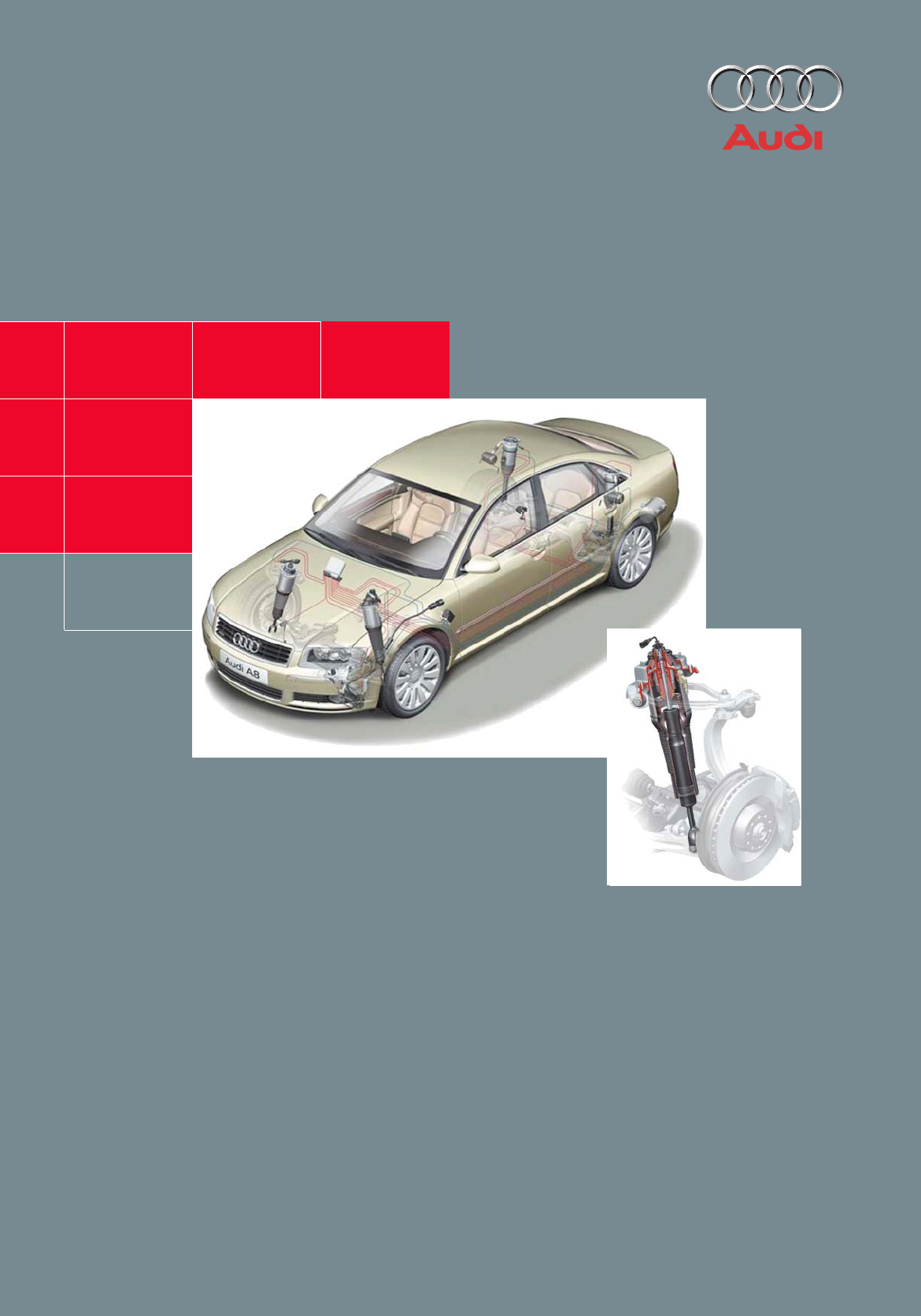
- System components 10
- Pneumatic spring 13
- Air supply unit 15
- Pressure build-up 19
- Pressure reduction 19
- System functions 24
- Interfaces 34
- Ancillary signals 39
- CAN High 39
- Control unit code 42
- System initialisation 42
- Final control diagnosis 43
- Measured value blocks 43
Summary of Contents
292Service292Home study program 292For internal company use onlyAll rights reserved, including the right to make technical changesCopyright* 2002 AUDI
10Air supply unitSolenoid valve blockwith pressure senderPneumatic struts, FAAdaptive air suspensioncontrol unitVehicle levelsender, FADash panel inse
11Pneumatic struts, RAAccumulatorVehicle level sender, RABody acceleration sender292_012
12System components292_013Hardware4E0 907 553 C * = Standard running gear4E0 907 553 D * = Sporty running gearControl unit J197The control unit is the
13Pneumatic springConstruction:The pneumatic spring is encased in an alu-minium cylinder. In order to prevent dirt from getting between the cylinder a
14292_016System componentsShock absorberConstruction:A twin-tube gas-filled shock absorber with continuous electrical control is used (ccontin-uous da
15Air supply unitThe air supply unit is installed at the front left of the engine compartment. This prevents any impairment of the acoustics in the pa
16System componentsSolenoid valve blockThe solenoid valve block contains the pres-sure sender and the valves for actuating the pneumatic springs and t
18System componentsPneumatic diagram292_020Air supply unitSolenoid valve block1Compressor V662 Air drier3a, 3b Non-return valves4 Exhaust throttle5 El
19Pressure build-upPressure reductionThe appropriate valves 9a, 9b and 9c, 9d and the electrical exhaust solenoid valve 5 are opened. The air can flow
The development of the running gear is subject to conflicting objectives. For now, besides "classic" aims such as function, driving safety,
20System componentsSenders (sensors)Compressor temperature sender G290Construction:An NTC resistor is housed in a small glass case.Function:The sender
21292_025Tabs for cri m pCable outletArrow forinstallationpositionBracketAcceleration senderIn order to achieve optimum damping for every driving cond
22System componentsRest condition: The seismic mass is situated exactly in the middle between the counter-electrodes. The two capacitors C1 and C2 hav
23Construction:The sender construction and the PIN designa-tion are the same as those of the allroad quat-tro (description in SSP no. 243).The four se
24System functionsGeneral control conceptChanges in level are effected by axle, with correction of differences in level between the left and right-han
25Notes
26System functions"automatic" mode (basic level)The suspension is oriented towards a more comfortable ride.Automatic motorway lowering of 25
27"lift""comfort""automatic""dynamic"292_053Acceptance level for selecting "lift" mode 50 mph (80 km
28System functionsControl concept for sporty running gear– Same levels but different damping maps for "dynamic", "automatic" and
29Control concept for special operating conditionsCorneringSuspension adaptation is interrupted during cornering manoeuvres and continued after-wards.
3ContentsPageCaution!Note!New!The home study program informs you about designs and functions. The home study program is not a Repair Manual!All values
30System functionsBraking manoeuvresDamping control is employed, particularly during ABS/ESP braking manoeuvres. Damp-ing is regulated as a function o
31Lifting-platform modeThe system recognises lifting-platform mode by evaluating the signals from the vehicle level sender and by the length of time t
32System functionsUsing a jack (service mode)There is no automatic recognition.Adaptive air suspension must be deactivated if a jack is to be used. Th
33Emergency running functionIf a failure of system components or signals is detected, the full functional reliability of the system is generally no lo
34InterfacesSystem overview of components with bus link (CAN, MOST)Diagnostic CANCAN comfortJ197 Adaptive air suspension control unitJ285 Control unit
35G76, G77, G78, G289 FA and RA vehicle level sendersG290 Compressor temperature senderG291 Adaptive air suspension pressure sender (integrated in sol
36J197 Adaptive air suspension control unit– System status (all)– Actuate warning lamp (5)– Actuate low level indicator (5)– Advance warning o
37Information which is transmitted by the adaptive air suspension control unitInformation which is received and evaluated by the adaptive air sus-pens
38InterfacesFunction diagramG76 Vehicle level sender, rear leftG77 Vehicle level sender, rear rightG78 Vehicle level sender, front leftG289 Vehicle le
398292_051Ancillary signalsCAN HighCAN Low12
4IntroductionBasicsThe basics for understanding air suspension systems are contained in home study pro-grams 242 and 243 and are of course also valid
40InterfacesOther interfacesThe wake-up signalto wake the adaptive air suspension control unit from sleep mode is transmitted by the comfort system ce
41The signal for headlight range controlThe adaptive air suspension control unit sends the headlight range control unit a CAN message about the moment
42ServiceControl unit codeThe code for both the standard and the sporty running gear is 15500.System initialisationThe system initialisation process i
43Final control diagnosisFinal control diagnosis checks the function of the compressor, the solenoid valves and the struts/shock absorbers.Diagnosis i
44Notes
292Service292Home study program 292For internal company use onlyAll rights reserved, including the right to make technical changesCopyright* 2002 AUDI
5Operation: Integration in the MMI means that operation is user-friendly, logical and easy to learn.(See description in the "Operation and dis-pl
6Operation and displayVehicle levelsThe A8 comes either with a standard running gear (adaptive air suspension) or a sporty run-ning gear (adaptive air
7292_006"lift" mode: + 25 mm+ 25 mm"lift" mode: Vehicle level is 25 mm higher than in "automatic" mode, comfort-oriented
8Operation and display"lift" mode: Level 25 mm higher than "automatic" mode of sporty running gear, sporty suspension.Sporty runni
9Operation and display systemThe process of switching from one mode to another and the display/monitoring of the system status all form part of the MM
More documents for Cars Audi 2003 A8


Related products and manuals for Cars Audi 2003 A8
 (36 pages)
(27 pages)
(37 pages)
(34 pages)
(80 pages)
(120 pages)
(92 pages)
(38 pages)
(313 pages)
(34 pages)
(6 pages)
(104 pages)
(23 pages)
(132 pages)
(40 pages)
(32 pages)
(4 pages)
(61 pages)
(66 pages)
(142 pages)
(36 pages)
(27 pages)
(37 pages)
(34 pages)
(80 pages)
(120 pages)
(92 pages)
(38 pages)
(313 pages)
(34 pages)
(6 pages)
(104 pages)
(23 pages)
(132 pages)
(40 pages)
(32 pages)
(4 pages)
(61 pages)
(66 pages)
(142 pages)
© 2020, manymanuals.com. All rights reserved. | 0.041 s |
 Manymanuals.com
 Manymanuals.de
 Manymanuals.fr
 Manymanuals.it
 Manymanuals.pl
 Manymanuals.cz
 Manymanuals.es
 Manymanuals-pt.com
Comments to this Manuals